
 Home
Home


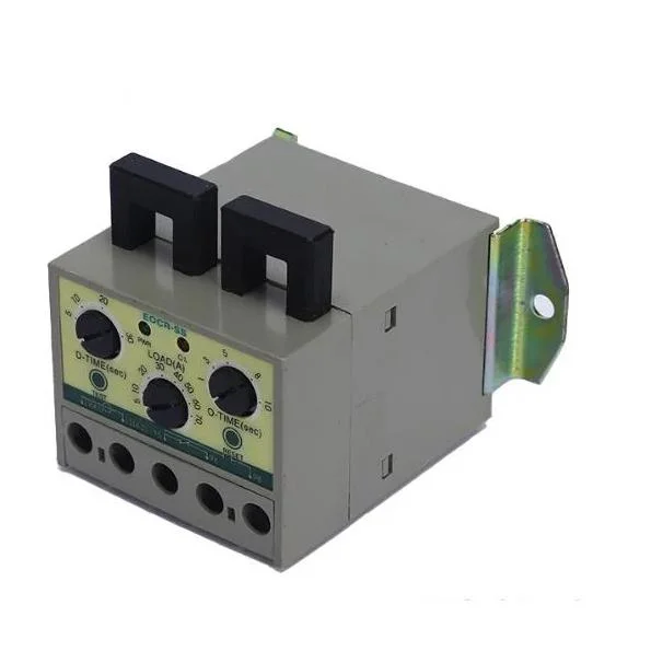
Electronic Motor Over Current Protector
Package Size 54.00cm * 65.00cm * 63.00cm Package Gross Weight 0.300kg Product Generalizes: HTHY-21 Motor Overcurrent Ele
Basic Info.
| Model NO. | HTHY-21 |
| Arc-extinguishing Medium | Relay |
| Installation | DIN-Rail |
| Structure | Electronic |
| Type | Relay |
| Function | Overcurrent Protection, Phase Loss and Phase Failure and Locked Rotor |
| Certification | ISO9001-2000, CE, CB, CCC |
| Models | 05, 30, 60 |
| Working Power Supply Are Three Phase | 180~440VAC |
| Working Power Supply Are Single Phase | 90~260VAC |
| -Rated Current | 6A,30A,60A |
| Transport Package | Exporting Carton |
| Trademark | LONGROAD/OEM |
| Origin | China |
| Production Capacity | 200000PCS/Month |
Packaging & Delivery
Package Size 54.00cm * 65.00cm * 63.00cm Package Gross Weight 0.300kgProduct Description
Product Generalizes:HTHY-21 Motor Overcurrent Electronic Protector is a super small overcurrent relay with definite time action characteristics. Using the main circuit phase line to pass through two transformers (CTs) to obtain the current sensing signal. When the load is abnormal, cut off the power supply of the control circuit through the action of the internal relay to protect the load. The utility model has the advantages of small size, light weight, anti-interference, noiseless, reliable performance, strong protection function,convenient installation and use, etc. It is mainly applicable to overload protection of motors, equipment, etc. 1.Function introduction: 1.1 It has overcurrent, phase loss, locked rotor protection functions. 1.2. Three different models (05, 30, 60) can be used to achieve protection in the range of 0.5~60A. If it exceeds 60A (maximum 800A), external transformer shall be used together. 1.3. Start delay, action delay and overload values can be set separately. 1.4. The working power supply are single phase 90~260VAC, three phase 180~440VAC, (24V, 36V, 110V, 660V power supply can be customized for production). 1.5. The two indicator lights (LED) respectively display the power status (green) and action status (red). 1.6. After the relay acts, it can be reset manually (press RESET button) and by power off. 1.7. This product has three different current models 05(0.5-6A), 30(3.0~30A),60(5.0~60A) 2.Setting method After the wiring is completed according to the typical wiring diagram, the relay shall be set as necessary to ensure the normal operation of the relay. The methods are as follows: 2.1 Before starting the motor, according to the actual starting time of the motor, set the D-TIME knob to this value (it is better to add 2~3 seconds more). If it cannot be determined, set the knob to the maximum value. 2.2 Adjust the action delay knob (O-TIME) and overcurrent setting knob (LOAD) to the maximum value. 2.3 Start the motor, and after the motor runs stably (i.e. exceeding the D-TIME value of the starting delay time), slowly turn the overcurrent setting (LOAD) counterclockwise until the red indicator light (LED) lights up, which is 100% of the actual running current value. Then turn the knob clockwise to the point where the red indicator just went out (within the setting time of the action delay O-TIME). This point is 103% of the actual operating current value. Continue to turn the overcurrent setting button (LOAD) clockwise to set it at a proper overcurrent value. (The recommended over-current value is between 110% and 125% of the actual operating current value) 2.4 Recalibrate the starting delay time (D-TIME) according to the normal starting operation of the motor. Generally, the set value is 2~3 seconds larger than the actual value. 2.5 Reset the action delay (O-TIME) time according to the actual situation. 2.6 After setting, press TEST button to check the setting result 3. Indicator status description 3.1 When the relay is powered on, the green indicator (LED) lights up, indicating that it has entered the normal state. 3.2 If the red indicator light is on during operation, it means that the protection function of the relay acts.
| Rated Current | 6A,30A,60A |
| working power supply are single phase | 90~260VAC |
| working power supply are three phase | 180~440VAC |
| models | 180~440VAC |

generalizesgeneralizesgeneralizes
Send to us